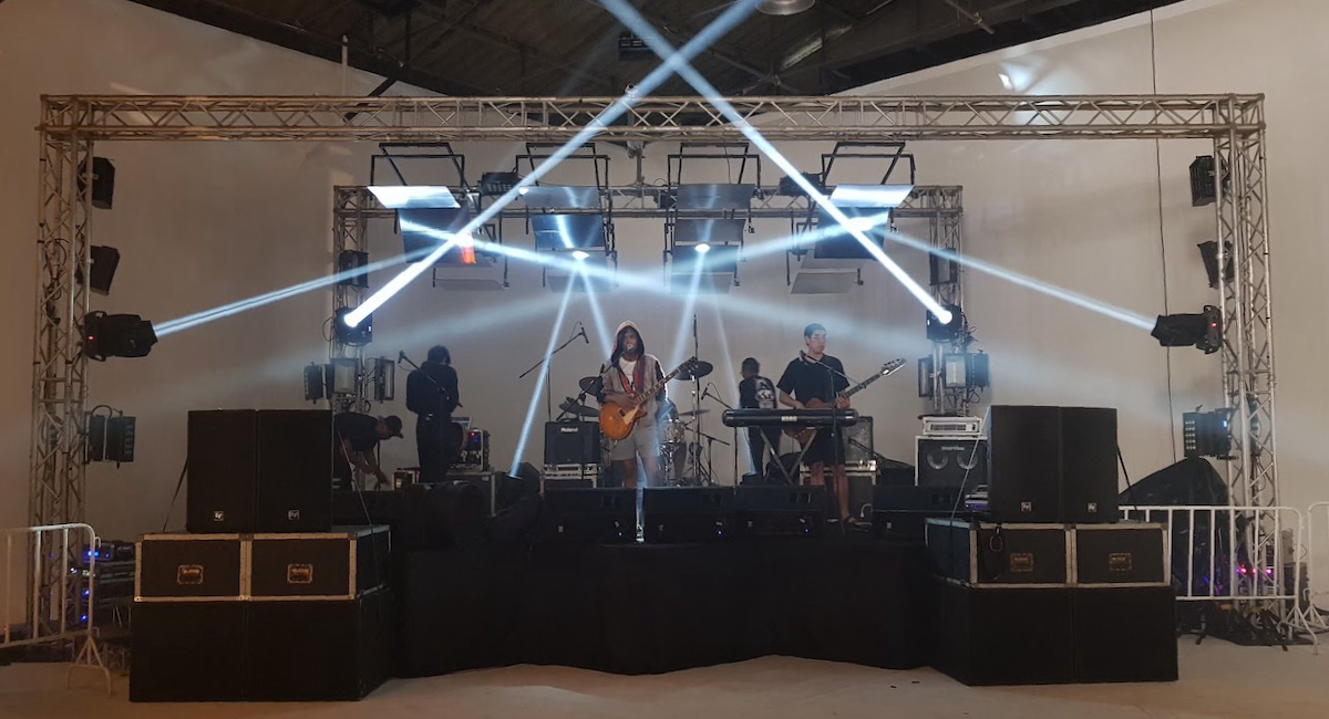
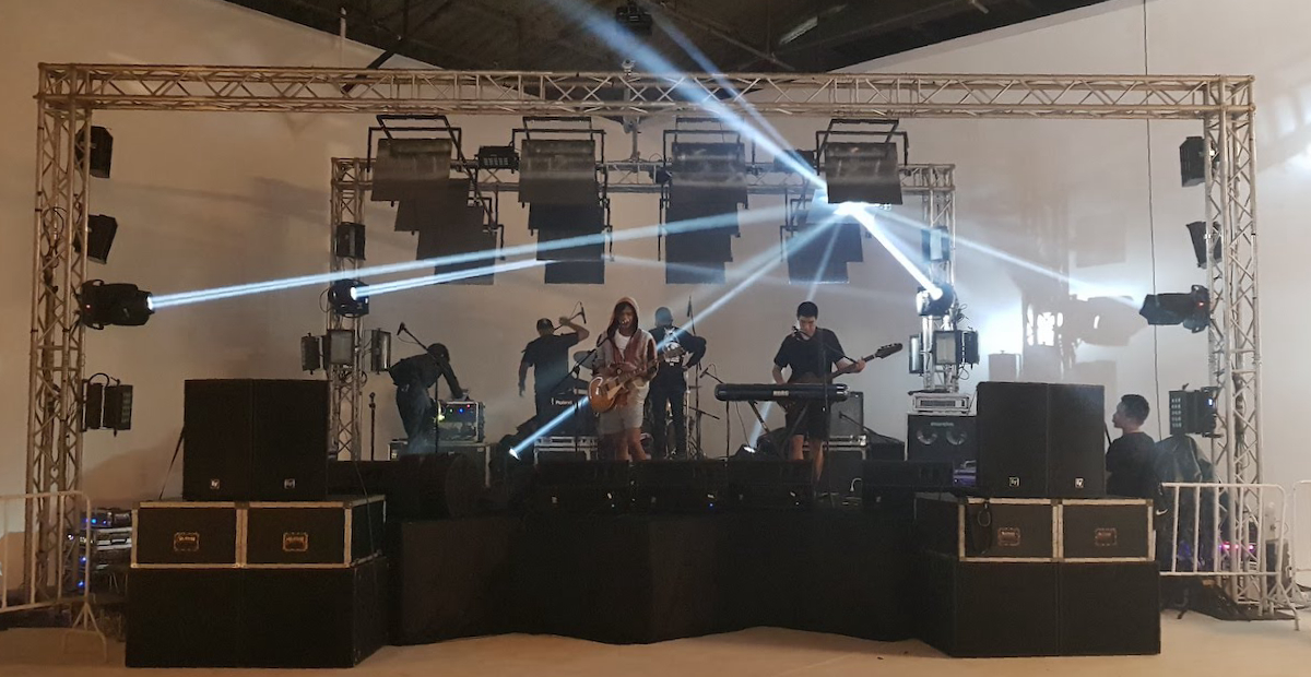
At AUTOSAVE, we always try different methods to achieve a new lighting experience. Apart from working with lighting in concert industry, we also do interactive art installation. We got an idea that we will make an art installation displaying in a concert. So, here Fungjai: ฟังใจ partnering with Joox music and Hennessy create a series of concert called "The primary colour series" #jooxtheprimarycolourseries consists of 3 concerts and Autosave is responsible for the last called #jooxmadfurious. We got River Rhyme, Mattnimare, Bomb at Track, and Lomosonic all the awesome band at G-VILLAGE on 10 Feb 2018.
I will try share everything as much as I can, both success and failure from making this installation. I believe knowledge should be shared, and I want to write this for myself, documenting, remembering, understanding, learning from mistake. I think perhaps sometime it is important more how we get there than the end result.
Start from an idea
16 controllable rotating mirrors as a roof of the stage, how about that!. "Right!, We can do that." I told my co-worker. At the time, I know nothing about controlling motors except servo but I know we can make this works from sketch.
Setting a limit : We use 16 of 0.5 amp 12v nema17 stepper motors with 16 drivers connect to arduino controlled from a computer using processing, using 0.5 amp because we already have this motors and a 12v power supply that will cover all the required power from hardware. Additionally, change mirrors to chrome/silver mirror sticker on polypropylene sheets (PP board), because stepper power is only 0.5 amp - we need light weight moving part.
After soul searching
Early mistakes
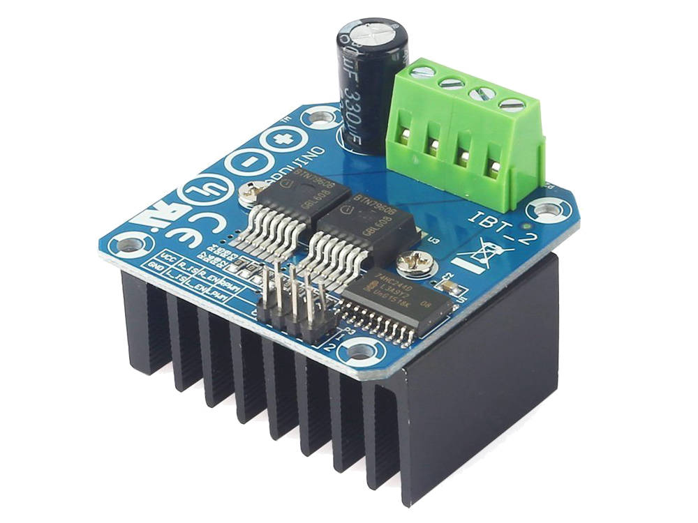
Brought a wrong driver : fork this sith!!, I brought 2 IBT-2 (BTS7960 chip) (picture above) that could drive 6-27V motor with maximum current of 43amp to try, I did not know at the time that this is for brush motors not suitable for stepper, should have done research better before jumping to buy things to try.
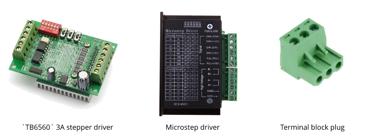
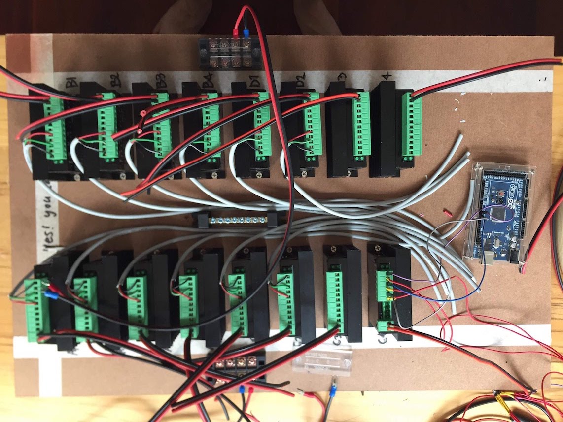
Brought a right driver but still wrong : brought TB6560 3A stepper driver, it's ok, working great, heat is not a problem. but we need something more solid easy to install, so I went Ban Mo electronic market in Bangkok again for micro stepper motor driver, it has terminal block plug, I know it's a good shit, it would be easy for our team to setup.
Concern length of wires : After we found that we may not able to place our control box on the ceiling catwalk, we know wiring is going to be long and hard.
PP board as mirrors are too big : the pp boards are ~60cm 70cm, thought it was alot smaller, but smaller size won't create good effect for the stage. Now, at this size the motor can't handle the weight, so we brought 17 of second-handed 1.5amp 12v nema17 stepper motors from Ban Mo electronic market, cheap, great, work. but it costs.
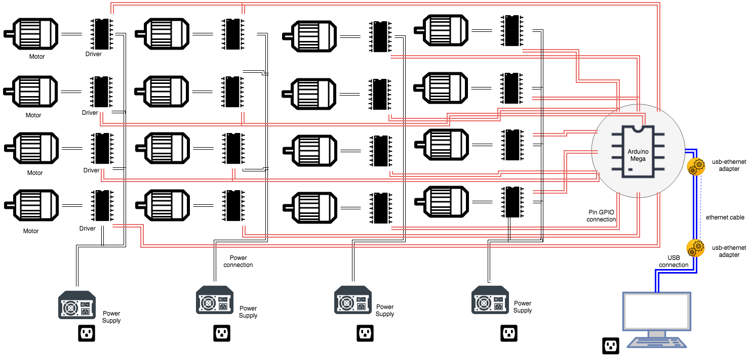
(it's not a good diagram, just a brief layout so my co-workers're on the same page)
System
After long soul searching, We arrived to the system conclusion (picture above), we use following:
Hardware
- Arduino Mega
- 16x 1.5A 12v nema17 stepper motors
- 16x MicroStepper driver
- Wiring 4-core for motor and 3-core for drivers about 200m in total
- USB to ethernet adapter
- cat5e 30m ethernet cable
- 4x 12v Power Supply
Software
- Processing : Sending signal to Arduino Mega via custom GUI.
- Control P5 : GUI library for Processing.
- Arduino : Making sure signal is recieved, then transfered moving patterns to each microstep driver motor.
I love coding. At autosave, most of our softwares are custom-made, because we can. I made this simulation before I were actually getting into hardware, the software actually sending position data but I did not write code on arduino, just want to simulate it. It turned out it's really hard to make it sync with real motor, since the motors did not sent any feedback rotation to the pc, so simulation you see in the video is no use at all, I removed it. and I did cheat!
wait whaaat
I cheated
> I put all the pattern on the arduino YES! the software did not send rotation pattern of each motor to arduino, that would be like sending an array position of 16 values on serial baud rate 11520. The software send signal which pattern is currently playing!! and when to stop . <= This save my time, I wrote it in a day. This is wrong in some level. Because first, pattern is limited - only available on arduino. Second, not flexible. Third, no speed up or down. but this method have only a benefit - It send a lot less serial packaged. it only send when pattern is change, pattern is stop, and moving individual motor. so less packaged, less error.
!!!!!
Two things about software that I still have a problem with.
- Sometime, after period of time, PC disconnects arduino or the other way around, IDK. I need to remove USB connection and change the USB port in order for PC to recognize it again, like arduino just dissappear.
- When I hold an arrow just to move a motor individually too long, PC disconnects arduino. I perhaps know the reason - it's because there is no
delay? signal flooding? but it's a software problem for sure.
IF ANYONE KNOW THE ANSWER TO THIS QUESTION, PLEASE...
Wiring
Essentially this need to be mentioned, because this is where usually error occurs and in sixteen, we use more than 200m wiring with 30m of ethernet connection this because of space limitation.
We use arduino mega. If we want to sent serial from a pc, we need USB connection between pc and arduino. But long USB wire is a problem, pc can't find the arduino if it is too long. To solve the problem, USB power adapter is required to amplify the signal. But what if you don't want to use it, because need another power plug. I accidentally found a solution while searching online for a 360 Kinect adapter on Lazada for the other project. Solution is to change USB to Ethernet cable using USB to lan adapter. That is much simpler and easy, no power necessary.
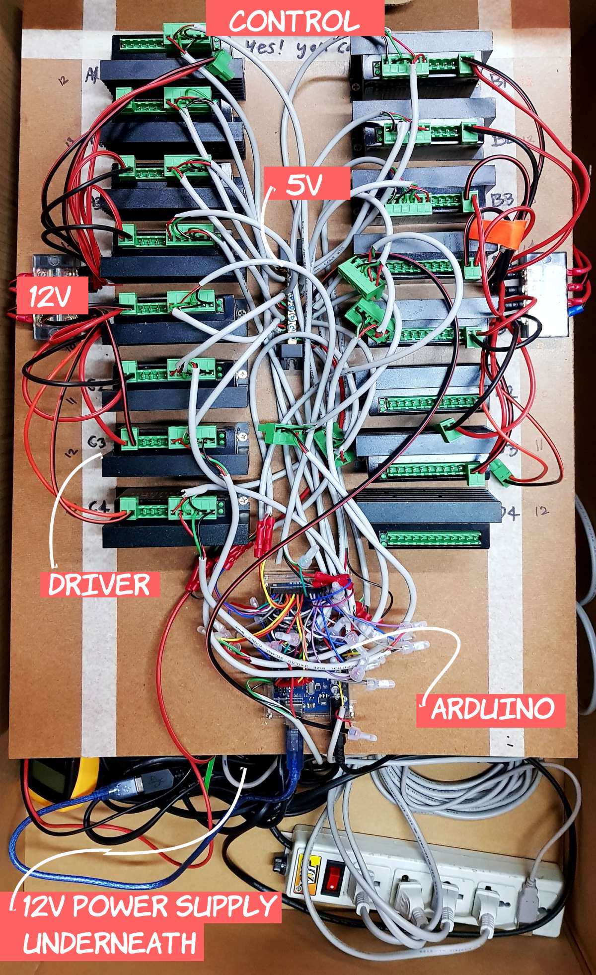
For the arduino mega, we placed it on a wooden sheet glue everything together, All GPIO connections to each driver as you can see from the upper picture. Arduino power are from 5V 2amp usb adapter to VIN pin and USB power from a pc. nothing magic.
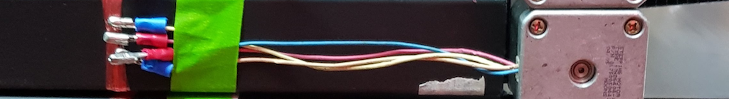
For the stepper drivers, we also placed it on the wooden sheet. Stepper driver need 2-wire for 12V power supply, 4-wire for the bipolar stepper motor and 6-wire to arduino (3 of this wires are from 5V power source which need to share GND with arduino, the other 3 from arduino - we use 3-core wire).
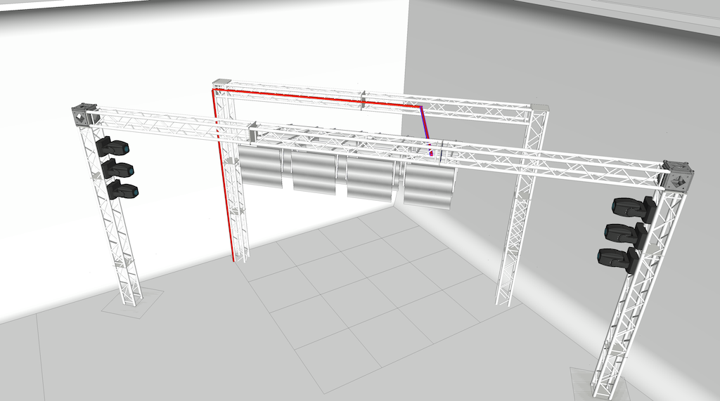
Then we did wiring from the driver to motor using 4-core wire, 200m in total. We calculated all the length from 3D software : SketchUp, we did draw the space in 3d software the exact size. So every cable had a number of row and col.
| _9 D1 | _10 D2 | _11 D3 | _12 D4 |
|---|---|---|---|
| _10 C1 | _11 C2 | _12 C3 | _13 C4 |
| _11 B1 | _12 B2 | _13 B3 | _14 B4 |
| _12 A1 | _13 A2 | _14 A3 | _15 A4 |
_number is the length of the wire it should be, A-D is Row (A is front, B is back of the stage). The number after alphabet is Col (1 is most left from audience point of view). eg. _9 D1 is the closest stepper to the controller.
Problems
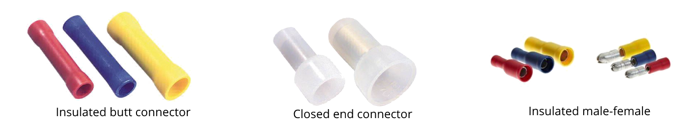
- Wire connectors make us headache, big time!. insulated butt connector! I don't even know how it got its name. we use this connector between arduino-->driver, and found that there're ~40% chance of error, eg. torn wires inside the connectors, or wires did not make a contact. We replaced with closed end connectors and it worked perfectly.
 There're also a problem with insulated male-female connector, We use this at the motors, so we're able to easily reconnect/remove wire, but they're not strong, after 2-3 removes, the male connector start to break.
 - Screw rigid couplings were correct size but it won't fit, therefore we changed to a bigger size but it loose later after running for ~30 mins. and this happened at the concert. We know this will happen, we use Superglue (cyanoacrylate) and epoxy on the connected surface, but it's just buying time before it loose again. The below video shows after running for period of time, the plates are unsynced.
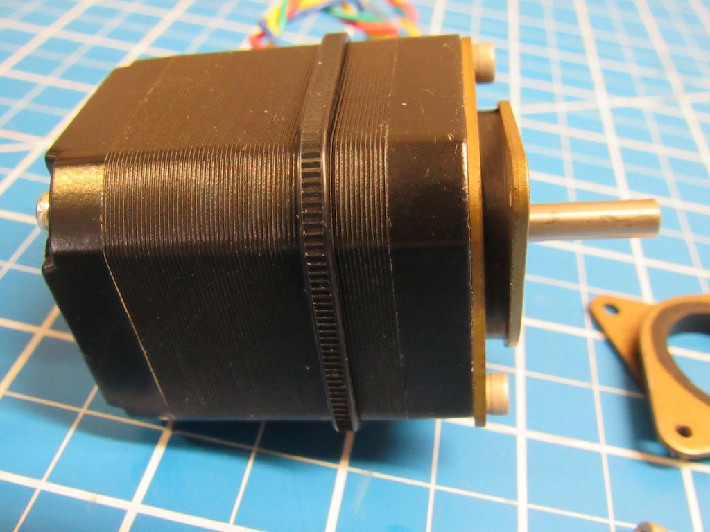
- Noise from running motor, this easily was fixed from the beginning. Luckily, the second-handed 1.5amp 12v nema17 stepper motors we brought all come with this rubber vibration damper
For the next shot
This is just to remind myself
- I will try push-in wire connectors . if it does not work, then close-end wire connector will do the job. For the connector at the motors, will try JST 4 pin connector.
- Able to control individually on midi device, and MA-wing.
- Screw rigid couplings need to be fixed. NOW NOW
- Research on why pc keep disconnecting on arduino
- More moving patterns, faster speed, fix the problem of drawing when stop.
- Feedback rotation is needed.

video documentary here, in Thai